

Framework overview and purpose
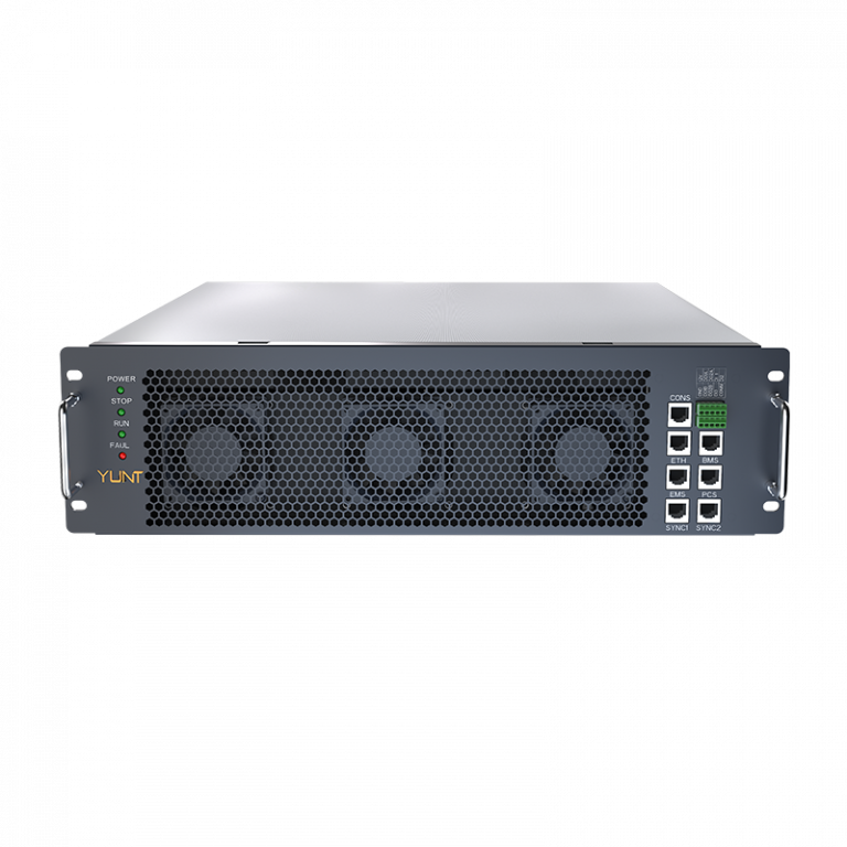
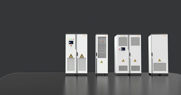
Structured validation is essential for production lines that must guarantee an immediate and verifiable anti-islanding disconnection response under IEEE 1547; this framework lays out the stages from component acceptance to on-line batch verification while aligning with commercial realities and regulatory expectations. For teams deploying factory automation and fielded assets, integrating commercial energy storage solutions into the validation matrix clarifies operational limits and acceptance criteria early. The approach emphasizes repeatable procedures, traceable test records, and harmonized firmware baselines to ensure every inverter leaves the line with predictable anti-islanding behavior and safe grid interaction.
Core validation stages
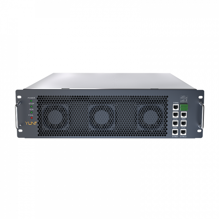
Validation divides into five discrete stages: incoming material inspection, bench functional tests, firmware configuration lock, automated production-line tests, and sampled field emulation. Each stage produces discrete pass/fail data stored in the manufacturing execution system. Bench tests verify basic parameters such as grid synchronization, SOC reporting, and relay coordination; on-line tests exercise trip thresholds and event logging. These stages reduce field failures and accelerate site acceptance tests when deploying energy storage system solutions into distributed grids.
Test methods, parameters and standards anchoring
Operational tests must map to IEEE 1547 requirements and to pragmatic test parameters used in factory and commissioning environments. For clarity, adopt explicit test procedures such as: a) Anti-Islanding Detection and Response Criteria — simulated grid loss with step voltage change of ±10% sustained for 0.5–1.0 s and verification of inverter cessation of energization; b) Frequency and Voltage Ride-Through Performance — controlled frequency drift at ±0.1–0.5 Hz/min with verification that protection logic isolates within defined windows; and c) Active Perturbation Tests — apply a ±0.5 Hz frequency perturbation and measure detection and trip within 0.5–2.0 s. These parameters align the production protocol with clauses addressing Voltage and Frequency Ride-Through Requirements and Anti-Islanding Test Procedures in IEEE 1547 documentation, ensuring test outputs are defensible during regulatory review.
Production-line integration and automation
Embed automated jigs that simulate grid loss, inject frequency perturbations, and record waveform traces. Use fixture-level telemetry to capture inverter firmware state, event logs, and trip timestamps. A concise operational production teardown should include {main_keyword} and {variation_keyword} as named inputs to the test matrix so traceability is preserved. Batch sampling must combine deterministic checks (every unit: relay actuation, basic sync) with statistical stress tests (1–5% of units: extended perturbation, hot-switch cycling). This balance keeps cycle time acceptable and preserves product safety margins.
Common mistakes and mitigations
Manufacturers often conflate functional pass with robust field behavior — passing a bench test does not guarantee proper behavior under grid irregularities. Avoid this by validating across a small range of grid impedances and load-step profiles in the factory. Another frequent error is insufficient firmware control: lock the production firmware branch and record checksum hashes before shipment. Finally, inadequate logging prevents post-incident analysis; ensure event logs capture pre-trip waveforms and state-of-charge markers for at least the prior 60 seconds — this aids root-cause work after a disconnection event. — These measures prevent repetitive field recalls and preserve brand credibility.
Real-world anchor and lessons learned
Operators in high-penetration markets such as California have documented the operational strain that unvalidated DER behaviors impose on system operators; production validation that mirrors those field conditions reduces commissioning time and regulatory friction. Experience shows that when manufacturers align factory test parameters with utility operational scenarios, site acceptance testing and interconnection are smoother and faster, and warranty incidents fall noticeably.
Advisory metrics for decision-makers
Three golden rules to evaluate any validation protocol: 1) Detection-to-Trip Latency — measure median and 95th-percentile trip times under controlled perturbations; 2) Field-Transferability Index — compare factory waveform logs to representative utility waveforms and require a minimum correlation score before shipment; 3) Firmware Traceability Ratio — maintain immutable records tying shipped firmware hashes to each serial number and test result. These metrics provide clear, auditable thresholds for procurement and quality teams. Trust in measurable outcomes; rely on documented evidence when negotiating interconnection agreements. YUNT. — Final thought.