

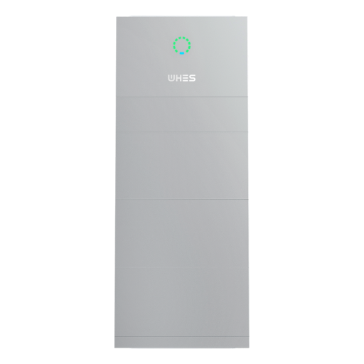
Data-driven kickoff: why compensation rates matter now
Grid operators and system designers increasingly tune frequency droop control to squeeze stability and flexibility out of batteries — from a backyard home energy storage system to multi-megawatt solar battery parks. The proof is in the outages and near-misses: California’s heatwave-driven rolling blackouts in 2020 highlighted how faster active power delivery and coordinated reactive support can keep feeders live when demand spikes. So the question isn’t just “how much” power a battery can deliver, it’s “how” it shares active and reactive duties under real grid stress.
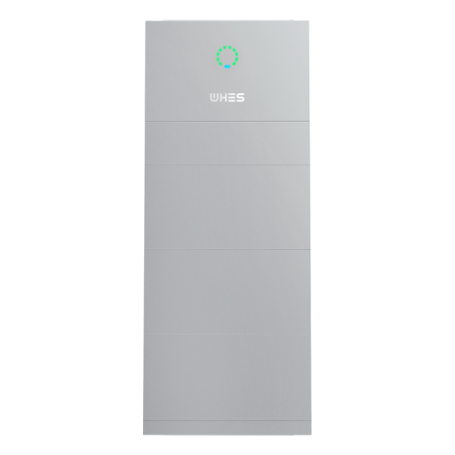
Core metrics: what engineers actually compare
When teams model compensation strategies they focus on a few measurable items: active power headroom (kW), reactive power capacity (kVAR), and droop slope (percent per Hz). Active power affects immediate load-following and frequency arrest; reactive power shapes voltage profiles on distribution feeders. In practical terms, an inverter’s ramp rate and its ability to provide both active and reactive output without tripping are the hard constraints. Those are the numbers you’ll feed into protection studies and dynamic simulations.
Scaling effects: residential battery vs multi‑MW parks
Scale changes the trade-offs. A single residential inverter will often prioritize state of charge and backup reserve over sustained reactive support — it’s built for customer resilience and peak shaving. By contrast, a multi‑MW solar battery can be configured for grid-forming duties and continuous reactive compensation alongside active smoothing. If you’re comparing projects, think in terms of control modes (grid-following vs grid-forming), inverter thermal limits, and available SoC margin. For smaller systems, residential battery storage often means simpler control stacks; larger sites demand coordinated droop tuning and communications for system-level stability.
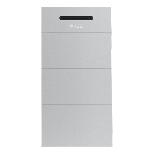
Control strategies and practical trade-offs
There are a few common approaches: proportionally split active/reactive setpoints, dynamic priority switching (active first during frequency events), and adaptive droop where slopes change with SoC or thermal state. Each strategy affects equipment and operations differently. For example, aggressive reactive support can heat power electronics and reduce available active power — and if you don’t model that, you end up with protection trips at the worst moment. Testing matters: run hardware-in-the-loop or factory acceptance trials that mirror your grid conditions — you’ll thank yourself later.
Don’t assume a single droop setting will work everywhere — site impedance, short-circuit capacity, and local voltage regulation all change the optimal split. —
Common mistakes that skew compensation performance
Teams often stumble over three avoidable issues: mismatched inverter ratings versus planned duty cycles, neglecting thermal derating during sustained reactive flows, and underestimating communication latency for coordinated control. Another classic is missing the human side: operators need clear dispatch logic during events, not a black-box controller. Simple fixes include conservative firmware settings during commissioning, clear SoC guardbands, and documenting acceptance tests tied to protection curves.
Advisory: three critical evaluation metrics (golden rules)
1) Dynamic response time and range — Measure how fast the system reaches commanded active/reactive setpoints and how much headroom is left at that speed. Short response time with sufficient range means effective frequency arrest without sacrificing voltage support.
2) Thermal and energy sustainability — Evaluate continuous reactive capability against inverter thermal limits and the expected SoC profile. A controller that commands reactive power without accounting for thermal derating will force derates or trips.
3) Grid-code compatibility and ride-through performance — Ensure your droop and compensation scheme meets local interconnection rules for low-voltage ride-through, frequency response, and fault behavior. Compliance avoids commissioning delays and potential curtailment.
Choosing settings that pass these three checks reduces field surprises and makes operation predictable — and that’s precisely where integrated solutions from practitioners who understand both customer needs and grid constraints add real value. WHES bridges that gap with design and deployment practices tuned for both home systems and utility-scale projects.
Practical, tested, and ready — the right droop settings keep the lights on and systems healthy. —